What are the components that make up a clutch?
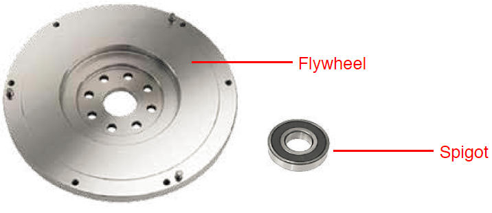
FLYWHEEL
The flywheel is one side of the vice. It is a big metal disc that bolts directly to the crankshaft. Its role is to:
• Provide a flat clamping surface for the clutch plate to match.
• Keep momentum. It is a heavy mass that keeps turning the crank.
• Take heat away from the clutch plate.
Because the flywheel is bolted directly to the crank, the flywheel will always spin at the same rate as the crank shaft of the engine. (Around the outside of the flywheel there is a ring gear. Although it is a part of the flywheel, ring gears have nothing to do with the clutch itself.
Some modern vehicles come fitted with Dual Mass Flywheels (DMF), more details about this can be found in the dual mass section of the FAQ).
GEARBOX INPUT SHAFT
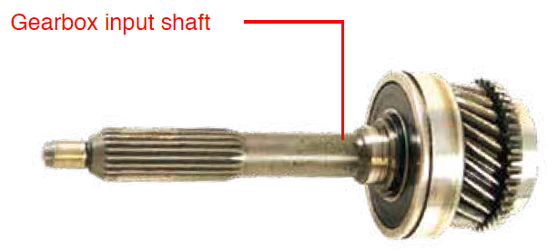
A small but very strong shaft. At one end is a locating pin that sits in the centre of the flywheel/crank. A spigot bearing sits in the centre of the flywheel, on the locating pin of the shaft. Because the input shaft is not bolted to the crank, it does not turn with the crank, it just uses it as a locating point.
The opposite end of the shaft is connected to the gearbox. Along the shaft you’ll find gear teeth, called the spline, that match the centre hole of the clutch plate.
The gearbox input shaft’s purpose is to:
• Line up the gearbox with the centre of the crank shaft, keeping the rest of the drive train straight and true to the crank.
• Give the clutch plate a direction to locate onto and position itself.
CLUTCH PLATE/DISC
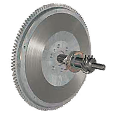
The clutch plate is a disc that slides over the gearbox shaft. The spline or teeth at the centre of the clutch plate match the teeth of the gearbox input shaft. When the clutch plate slides over the shaft, the matching spline teeth mean the clutch plate is keyed or locked into the gearbox input shaft, and is positioned flat to the flywheel.

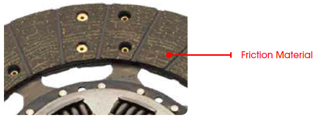
Around the outside of the clutch plate, on both sides, there is a hoop of friction material. The friction material riveted to the disc is designed to grip the flywheel. Because of the interlocking spline, the clutch plate and gearbox input shaft will then turn together.
‘When things rub together friction comes into play. In some cases you don’t want friction, so a lubricant is used. In other cases you want the friction and use materials to maximise it to achieve grip. Examples of friction material include brake pads, tyres and the material on clutch plates.’
FRICTION MATERIAL
Friction material is on either side of the clutch plate. Organic material is dark in colour and feels progressive as it is clamped. Ceramic material is generally in the shape of buttons and grips quickly, making it a slightly harsher than organic material.
CUSHIONING
The term cushion is used to describe the effect of the segments placed between the friction material. They are a type of wave washer that “cushions” the clamping force as it is applied. By cushioning the clamping force it feels progressive and smooth for the driver.

DAMPENING
The springs in the centre of the clutch plate absorb the pulsations of the engine. They “dampen” out the vibration and provide a progressive take up of the torque.
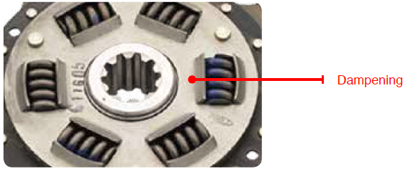
The type of friction material, cushioning and dampening used in a clutch plate has a big impact on how comfortable the clutch is to use. Taking these measures out will provide a quicker take up of torque, but the trade-off is a less comfortable drive. Consequently, race style clutches are very harsh to use, but transmit torque quickly.
COVER ASSEMBLY
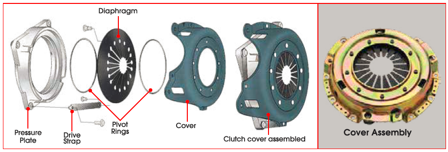
The cover assembly bolts onto the flywheel and OVER the clutch plate. The purpose of the cover assembly is to carry the matching surface (a heavy metal casting) for the flywheel, and a spring loaded system that pushes the casting towards the flywheel. Together the cover assembly and flywheel work just like a vice and work together to clamp down onto the friction material of the clutch plate. When the cover is bolted to the flywheel, its default position is clamped. The vice is tightly clamped onto the clutch plate.
ACTUATION SYSTEM
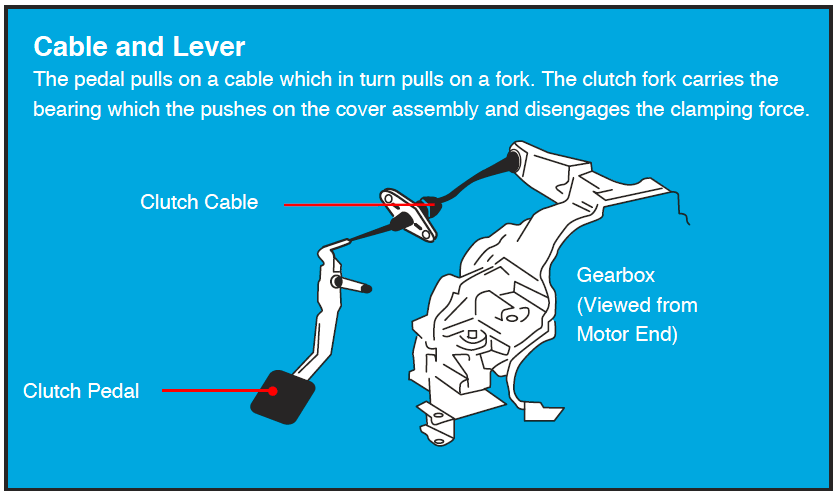
To disconnect the clutch, or let go of the torque, there is an actuation system which begins at the pedal and ends at the clutch cover assembly.
Engaging the clutch pedal is the same as winding back one side of the vice. When the clutch pedal is pushed, it will works a series of connected parts that ends with a push onto the spring loaded part of the cover assembly. The spring load is taken off and because the clutch plate is no longer clamped to the flywheel, it will stop spinning at the same rate as the crank. It means you have disconnected drive. Remember the locating pin of the gearbox input shaft is just a locating pin. It will sit in the flywheel, but is not bolted to it so it will not spin at the same rate.
BEARING
The bearing is fixed to the clutch fork on one side and has a surface which spins on the other. As the bearing is pushed onto the cover the surface spins, minimising the stresses and strains on the two parts.
HYDRAULICS
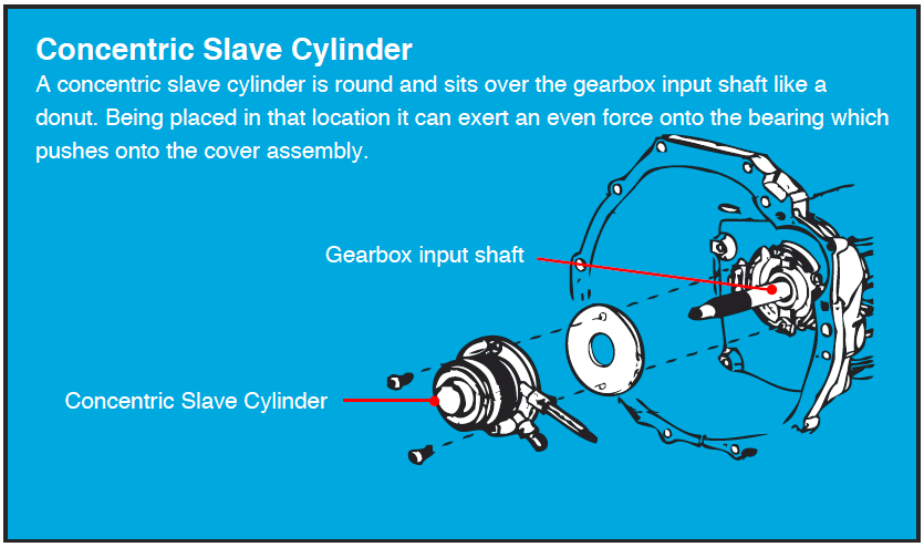
More recently hydraulics have been used for actuation systems. A hydraulic system adds a clutch master and slave to the actuation system. Instead of a cable, the pedal acts on the Master cylinder which increases pressure in a line. The increased pressure activates a slave cylinder which pushes onto the bearing and activates the clutch.
